

本文建置的架構
⇄
⇄
- 協定:WireGuard / UDP
- 用途:遠端存取
- 方式:分割通道
- 用戶端:官方 WireGuard for Windows
概觀
概觀與事前準備 #
OPNsense 上的 WireGuard 是結合Instance(伺服器端虛擬介面設定)與Peers(獲授權的連線對象)來設定的。OPNsense 官方文件建議將通道位址設計為獨立網路,就如同存在一個獨立的實體介面一般。[1][2]
本文目標 #
讓 Windows 電腦能透過 WireGuard 連線至 OPNsense,安全地存取 LAN 內的 NAS、RDP、SSH 與業務系統。
採用的連線方式 #
並非將整個網際網路的用戶端流量都送入 VPN,而是採用分割通道,僅將前往 LAN 的流量送入通道。
不過 Instance/Peer/General/Firewall 的概念架構是一致的。
- 可登入 OPNsense 管理介面
- WAN 側 UDP 51820 埠可正常使用
- 若 OPNsense 位於上游路由器之後,可將 UDP 51820 轉發至 OPNsense 的 WAN
- 可配置與目標 LAN 網段不重疊的 WireGuard 網路
- 可在 Windows 用戶端安裝官方 WireGuard for Windows
範例設計
範例設定 #
為求說明一致,本文採用以下範例。這些數值僅供參考,實際部署時請替換為貴組織的位址配置方案。
| 項目 | 值 | 意義 |
|---|---|---|
| LAN | 192.168.10.0/24 | 公司或家庭內部網路 |
| WireGuard 網路 | 10.10.10.0/24 | VPN 通道專用網段 |
| OPNsense 通道 IP | 10.10.10.1/24 | 設定於 Instance 上的位址 |
| Windows 用戶端 IP | 10.10.10.2/32 | 指派給 Peer 的專屬位址 |
| 公開主機名稱 | vpn.example.jp | WAN 的公開 IP 或 DDNS 名稱 |
| 接聽埠 | 51820/UDP | WireGuard 接聽埠 |
10.10.10.2/32
10.10.10.0/24
10.10.10.1/24
192.168.10.0/24
10.10.10.1/24)設定,伺服器端 Instance 應避免使用 /32 或 /128。[1]步驟 1
在 OPNsense 端建立 WireGuard Instance #
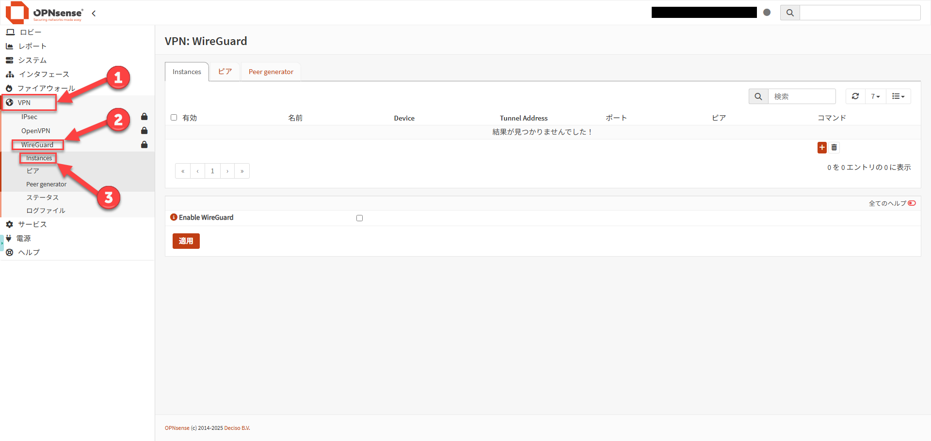
| 項目 | 設定範例 | 備註 |
|---|---|---|
| Enabled | 勾選 | 啟用 |
| Name | HomeWireGuard | 任意可辨識的名稱 |
| Public Key/Private Key | 自動產生 | 以齒輪圖示產生新金鑰 |
| Listen Port | 51820 | 與其他服務不衝突的 UDP 埠 |
| MTU | 1420 | PPPoE 環境建議設為 1412,以避免相容性問題[1] |
| Tunnel Address | 10.10.10.1/24 | WireGuard 專用網段 |
| Peers | 留空 | 此階段先留空,之後再建立 Peer |
| DNS Server | 留空 | 即使在 Advanced 模式下,通常也建議留空。設定此項會覆寫 OPNsense 本身的 DNS 設定。[1] |
儲存後再次開啟 Instance,並記下Public Key。
此公鑰即為稍後在 Windows 用戶端設定中需要輸入的伺服器端公鑰。[1]
步驟 2
為用戶端建立 Peer #
目前的 OPNsense 文件建議使用Peer generator,以便將設定散布給多個用戶端。它可選擇 instance、儲存 endpoint、自動指派位址並產生 Config 文字,而 OPNsense 上僅保存公鑰。由於私鑰不會保留在 OPNsense 上,請務必妥善保存產生的設定檔。[2][3]
建議流程:使用 Peer generator #
- 開啟
VPN > WireGuard > Peer generator。 - 選擇目標 Instance,輸入用戶端名稱、連線目的地 FQDN/埠、所需網路及 DNS。
- 指派如
10.10.10.2/32之類的位址作為用戶端專屬位址。目前的實作也支援自動指派位址。[3] - 建議將 Keepalive 間隔設為 25 秒(從跨越 NAT 與防火牆維持連線的角度考量)
- DNS 通常留空;但若需要透過 VPN 目的地的 DNS 伺服器解析主機名稱,可在此指定。
- 勾選 Enable WireGuard(啟用 WireGuard)
- Store and generate next(儲存並產生下一步):儲存公開資訊,複製產生的Config,並安全地儲存為
client-windows.conf。接著執行Apply,於Peers畫面套用。[2]
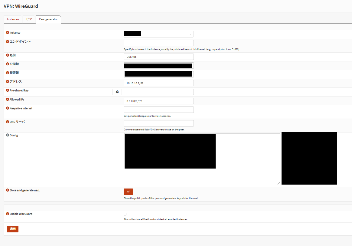
若重新產生,也需在 Windows 端重新匯入設定檔。[2]
手動建立 Peer #
若不使用 Peer generator,可在 VPN > WireGuard > Peers 建立新的 Peer,並設定用戶端公鑰與用戶端使用的 /32 位址。[1]
| 項目 | 設定範例 | 備註 |
|---|---|---|
| Enabled WireGuard | 勾選 | 啟用 |
| Name | Windows-Laptop-01 | 可識別裝置的名稱 |
| Public Key | 用戶端公鑰 | 在 Windows 端產生的金鑰 |
| Allowed IPs | 10.10.10.2/32 | 指派給此用戶端的專屬位址 |
| Pre-shared Key | 選用 | 可作為額外的安全措施[2] |
手動建立 Peer 後,回到原本的 Instance,關聯已建立的 Peer,儲存並執行Apply。[1]
手動建立 client-windows.conf 範本
若使用通道內 DNS,請確認 DNS 目的地已包含在 AllowedIPs 中。[1]
步驟 3
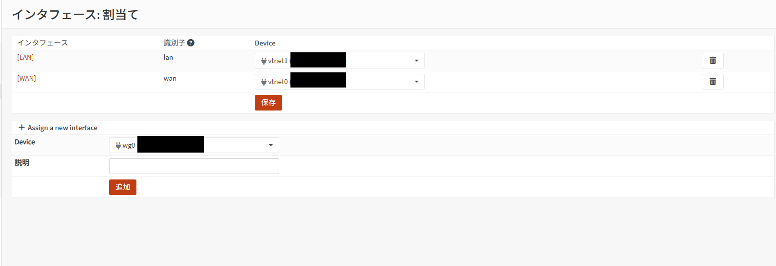
指派並啟用介面 #
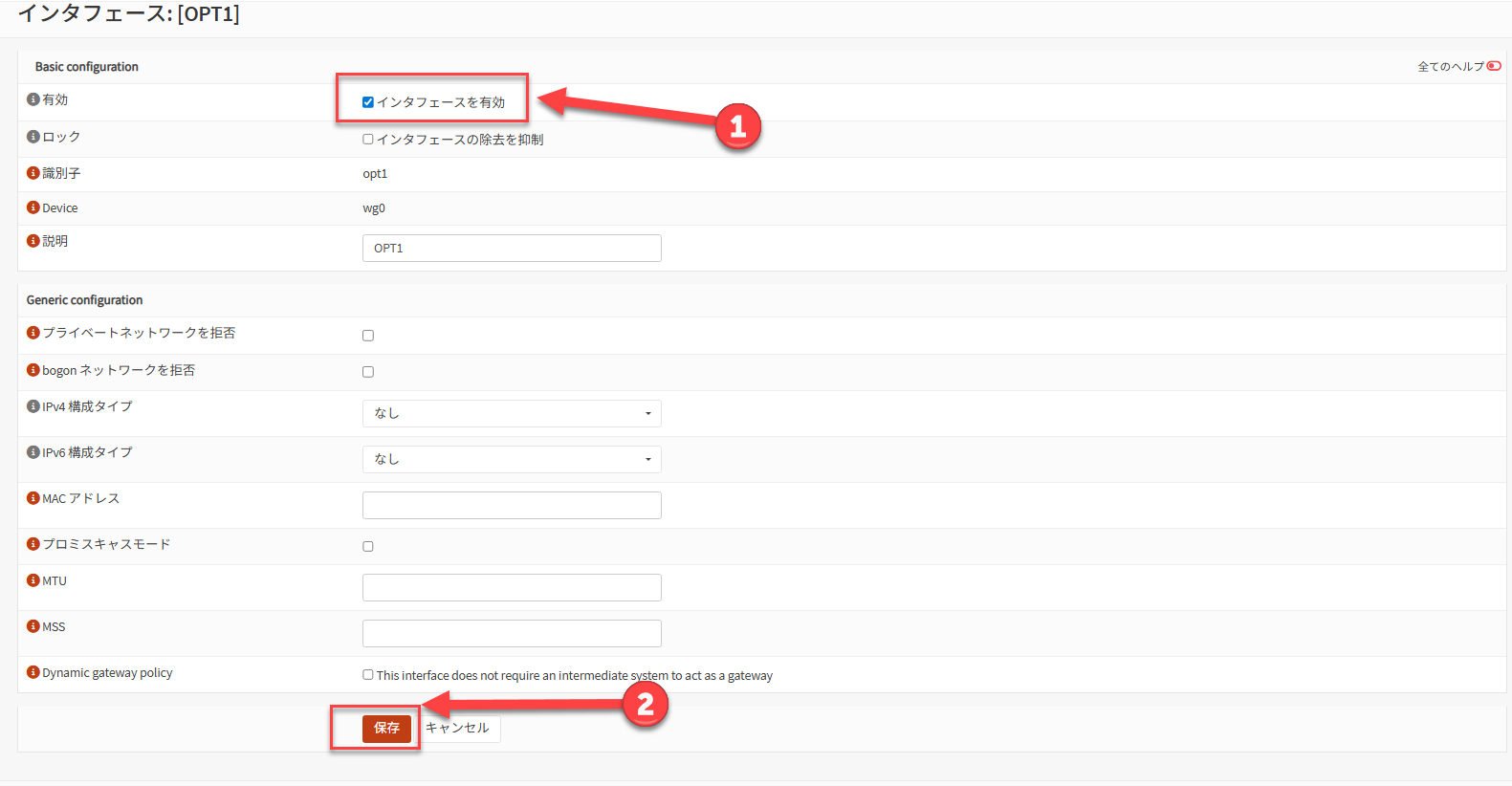
| 項目 | 設定範例 | 備註 |
|---|---|---|
| Enable | 勾選 | 啟用該介面 |
| Description | HomeWireGuard | 方便在建立規則時辨識 |
| IPv4 Configuration Type | None | 不手動設定 IP |
| IPv6 Configuration Type | None | 僅在需要時設定 |
OPNsense 官方指引指出,不需要在指派的介面上直接設定 IP;WireGuard 重新啟動後,Instance 中輸入的通道位址會自動反映。[1]
步驟 4
建立防火牆規則 #
官方流程採用兩階段做法:在 WAN 側允許 UDP 以建立通道,再在 WireGuard 介面側允許已核准的目的地。[1][2]
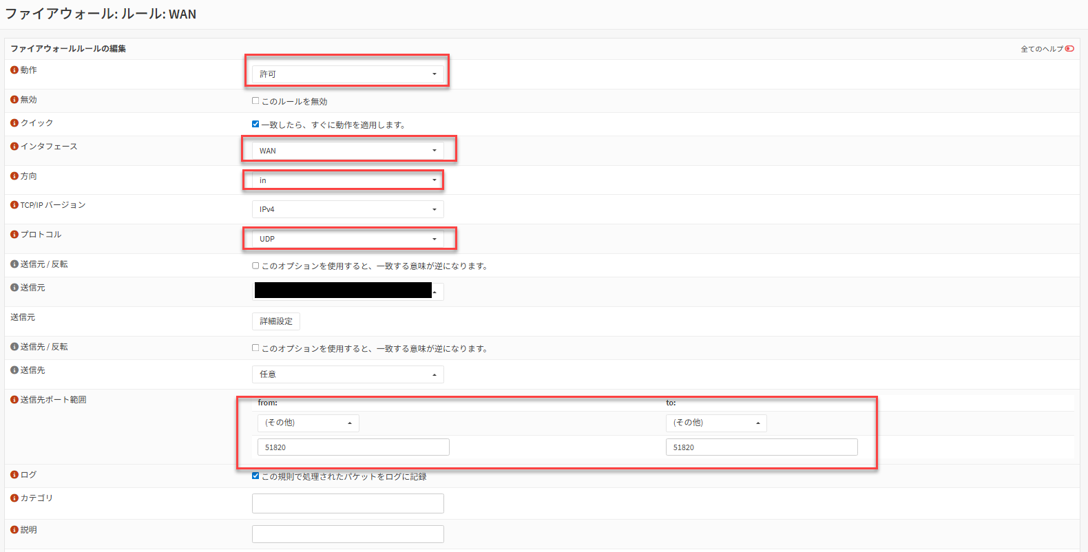
WAN 側規則 #
| 項目 | 設定範例 | 備註 |
|---|---|---|
| Action | Pass | 允許接收 |
| Interface | WAN | WAN 接收側 |
| Protocol | UDP | WireGuard 使用 UDP |
| Destination | WAN address | 自身的 WAN |
| Destination Port | 51820 | 需與 Instance 的 Listen Port 一致 |
| Description | Allow WireGuard | 可選填 |
WireGuard 介面側規則 #
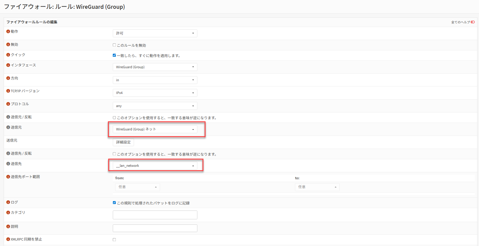
| 項目 | 設定範例 | 備註 |
|---|---|---|
| Action | Pass | 允許通道流量 |
| Interface | HomeWireGuard | 已指派的 WireGuard 介面 |
| Protocol | any | 初期用於連線測試時可接受 |
| Source | HomeWireGuard net | 通道網路 |
| Destination | 192.168.10.0/24 | 先僅允許 LAN |
OPNsense 官方指引允許將 WireGuard 規則的目的地設為 any,但在實際運維中,建議僅限制在必要的子網路與伺服器。[1]
PPPoE 環境或部分 TCP 通訊問題的 MTU/MSS 調整
官方指引中有在 PPPoE 環境將 Instance MTU 降低至 1412 的範例,並進一步指出可視需要透過 Firewall > Settings > Normalization 加入 MSS clamping。當發生僅 TCP 不穩定或僅網頁存取失敗等症狀時,此設定有效。[1]
| 項目 | 設定範例 |
|---|---|
| Interface | WireGuard (Group) |
| Description | WireGuard MSS Clamping IPv4 |
| Max MSS | 1380(PPPoE 時:1372) |
步驟 5
將設定部署至 Windows 用戶端 #
在 Windows 端,使用官方 WireGuard for Windows是最簡單的方式。安裝程式可從 WireGuard 官方網站取得。[4]
- 安裝 WireGuard for Windows。
- 準備從 OPNsense Peer generator 儲存的
client-windows.conf。若為手動建立,請使用前面提供的範本。 - 將設定檔匯入 WireGuard for Windows。
- 啟用目標通道並開始連線。
client-windows.conf
將如 192.168.10.0/24 這樣的 LAN 網段納入 AllowedIPs 中,就只有該目的地會經由通道傳送。若想讓用戶端所有流量都經由 VPN 傳送,依官方指引可使用 0.0.0.0/0 或 ::/0,但同時也需要在 OPNsense 端進行額外的 NAT/路由設計。[1]
步驟 6
連線驗證 #
- 在 Windows 用戶端啟用通道
- 測試與
10.10.10.1(OPNsense 通道 IP)的連線 - 嘗試以
ping、RDP、SSH 等方式連線至代表性的 LAN 主機(例如:192.168.10.10) - 視需要測試名稱解析,確認 DNS 是否正常運作
- 在
VPN > WireGuard > Status檢查交握(handshake)與收發統計[2]
運維
正式對外開放前應加強的安全措施 #
疑難排解
連線失敗時的檢查清單 #
未出現交握(handshake)
首先檢查 WAN 側 UDP 51820 是否允許通過、上游路由器的埠轉發、用戶端 Endpoint 的 FQDN/埠是否正確,以及用戶端是否存在明顯的時間偏差。
已出現交握但 LAN 無法連線
請檢查 Peer 的 Allowed IPs、用戶端的 AllowedIPs,以及 WireGuard 介面規則的目的地。OPNsense 官方文件也指出,Allowed IPs 設定錯誤會導致封包被靜默丟棄。[2]
ICMP 正常但部分網頁或 TCP 流量不穩定
請懷疑是 MTU/MSS 造成的影響。若為 PPPoE,可嘗試將 Instance MTU 設為 1412,並使用 Normalization 的 MSS clamping。[1]
僅 DNS 失敗
請確認用戶端指定的 DNS 目的地已包含在 AllowedIPs 中。若 Unbound DNS 是以「所有介面」方式登錄,新增 WireGuard 介面後需要重新載入(reload)Unbound。[1]
找不到 WireGuard 選單/畫面看起來不一樣
請檢查版本差異。Peer generator 部分在 24.1 系列中經歷了多次漸進式改良,UI 外觀與項目配置會因版本而異。[3]
來源
參考資料 #
- OPNsense Documentation, WireGuard Road Warrior Setup
https://docs.opnsense.org/manual/how-tos/wireguard-client.html - OPNsense Documentation, Virtual Private Networking > WireGuard
https://docs.opnsense.org/manual/vpnet.html - OPNsense Documentation, 24.1 “Savvy Shark” Series(包含 Peer generator 相關更新)
https://docs.opnsense.org/releases/CE_24.1.html - WireGuard Official, Installation
https://www.wireguard.com/install/