
Network How-To

A practical guide to configuring OPNsense at home, branch offices, or within your company as a WireGuard server and securely connecting from Windows PCs.
This article assumes a split tunnel configuration for use cases of “accessing internal LANs and home networks.” The procedure framework follows OPNsense official WireGuard Road Warrior Setup, general WireGuard documentation, and the official Windows installer guide.[1][2][4]
Configuration built in this article
⇄
⇄
- Protocol: WireGuard / UDP
- Purpose: Remote access
- Method: split tunnel
- Client: Official WireGuard for Windows
Overview
Overview and Prerequisites #
WireGuard on OPNsense is configured by combining an Instance (server-side virtual interface settings) with Peers (authorized connection partners). OPNsense official documentation recommends designing tunnel addresses as an independent network, as if a separate physical interface exists.[1][2]
Goal of this article #
Enable a Windows PC to connect to OPNsense via WireGuard and securely access NAS, RDP, SSH, and business systems within the LAN.
Connection method assumed #
Client traffic for the entire Internet is not sent through the VPN; instead, a split tunnel is adopted where only LAN-bound traffic is sent through the tunnel.
However, the conceptual structure of Instance / Peer / General / Firewall remains consistent.
- You can log in to the OPNsense management UI
- UDP port 51820 is available on the WAN side
- If OPNsense is behind an upstream router, you can forward UDP 51820 to the OPNsense WAN
- You can provision a WireGuard network that does not overlap with the target LAN segment
- You can install the official WireGuard for Windows on the Windows client
Sample Design
Sample Configuration #
The explanation in this article uses the following example for consistency. These values are samples only; replace them with your organization’s address scheme in production.
| Item | Value | Meaning |
|---|---|---|
| LAN | 192.168.10.0/24 | Internal corporate or home network |
| WireGuard Network | 10.10.10.0/24 | VPN tunnel dedicated segment |
| OPNsense Tunnel IP | 10.10.10.1/24 | Address set on Instance |
| Windows Client IP | 10.10.10.2/32 | Unique address assigned to Peer |
| Public hostname | vpn.example.jp | Global IP or DDNS name of WAN |
| Listen Port | 51820/UDP | WireGuard listening port |
10.10.10.2/32
10.10.10.0/24
10.10.10.1/24
192.168.10.0/24
10.10.10.1/24, avoiding /32 or /128 on the server-side Instance.[1]Step 1
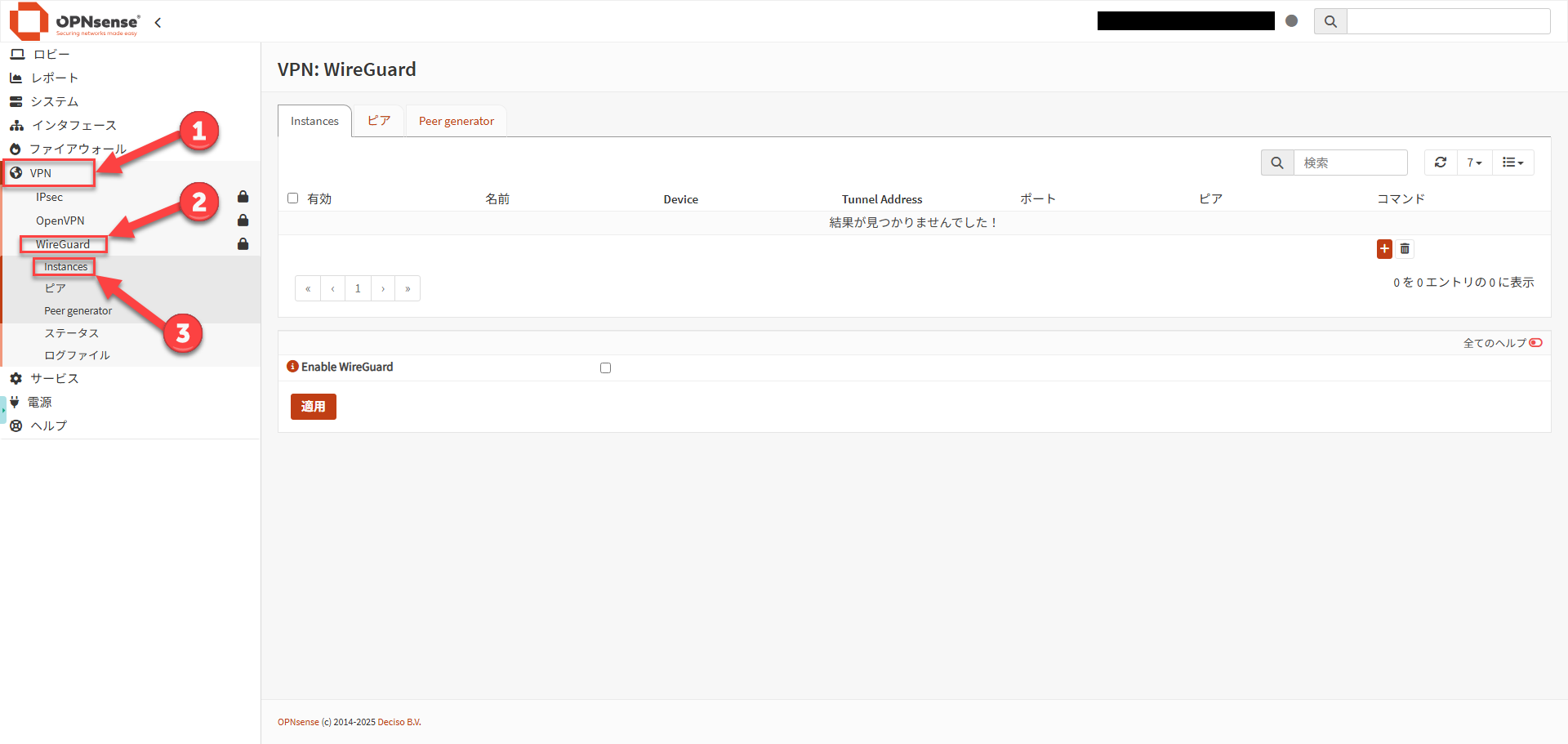
Create a WireGuard Instance on the OPNsense side #
| Item | Setting example | Notes |
|---|---|---|
| Enabled | Checked | Enable |
| Name | HomeWireGuard | Any identifying name |
| Public Key / Private Key | Auto-generated | Generate new with gear icon |
| Listen Port | 51820 | UDP port with no conflicts with other services |
| MTU | 1420 | Consider 1412 for PPPoE[1] |
| Tunnel Address | 10.10.10.1/24 | WireGuard dedicated segment |
| Peers | Blank | Leave empty at this stage to create Peer first |
| DNS Server | Blank | Even in Advanced mode, typically leave blank. Setting this overrides OPNsense’s own DNS configuration.[1] |
After saving, open the Instance again and record the Public Key.
This public key is the server-side public key to enter in the Windows client settings later.[1]
Step 2
Create a Peer for the client #
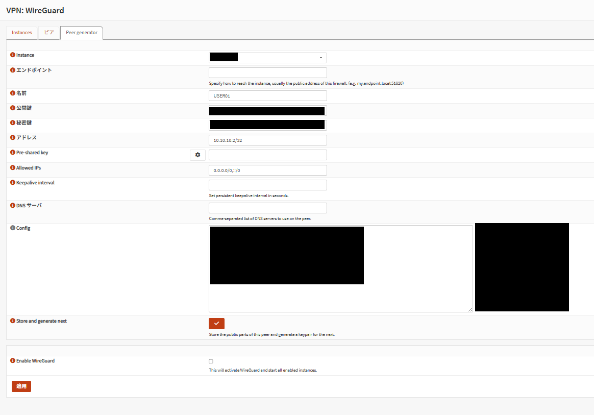
Current OPNsense documentation recommends using Peer generator for distributing configuration to multiple clients. It enables instance selection, endpoint saving, automatic address assignment, and Config text generation, with only the public key stored on OPNsense. Since the private key is not retained on OPNsense, securely store the generated configuration.[2][3]
Recommended procedure: Using Peer generator #
- Open
VPN > WireGuard > Peer generator. - Select the target Instance and enter the client name, connection destination FQDN/port, required networks, and DNS.
- Assign an address like
10.10.10.2/32as a client-specific address. Automatic address assignment is also available in the current implementation.[3] - Keepalive interval of 25 seconds is recommended (from a connection persistence perspective across NAT and firewalls)
- DNS is typically blank; however, if you need host name resolution via the VPN destination’s DNS server, specify it here.
- Check Enable WireGuard
- Store and generate next to save public information, copy the generated Config, and securely save it as
client-windows.conf. Then run Apply on thePeersscreen.[2]
If you regenerate, also reimport the configuration file on the Windows side.[2]
Manual Peer creation #
If you do not use Peer generator, create a new Peer at VPN > WireGuard > Peers, and set the client public key and /32 address for client use.[1]
| Item | Setting example | Notes |
|---|---|---|
| Enabled WireGuard | Checked | Enable |
| Name | Windows-Laptop-01 | A name that identifies the device |
| Public Key | Client public key | Key generated on Windows side |
| Allowed IPs | 10.10.10.2/32 | Unique address assigned to this client |
| Pre-shared Key | Optional | Available as additional security measure[2] |
After manually creating the Peer, return to the original Instance, associate the created Peer, save, and run Apply.[1]
Manual creation client-windows.conf template
If using tunnel DNS, ensure the DNS destination is included in AllowedIPs.[1]
Step 3
Assign and enable the interface #
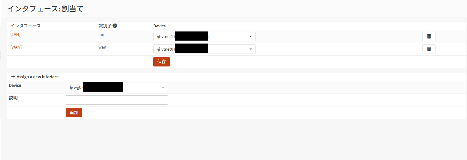
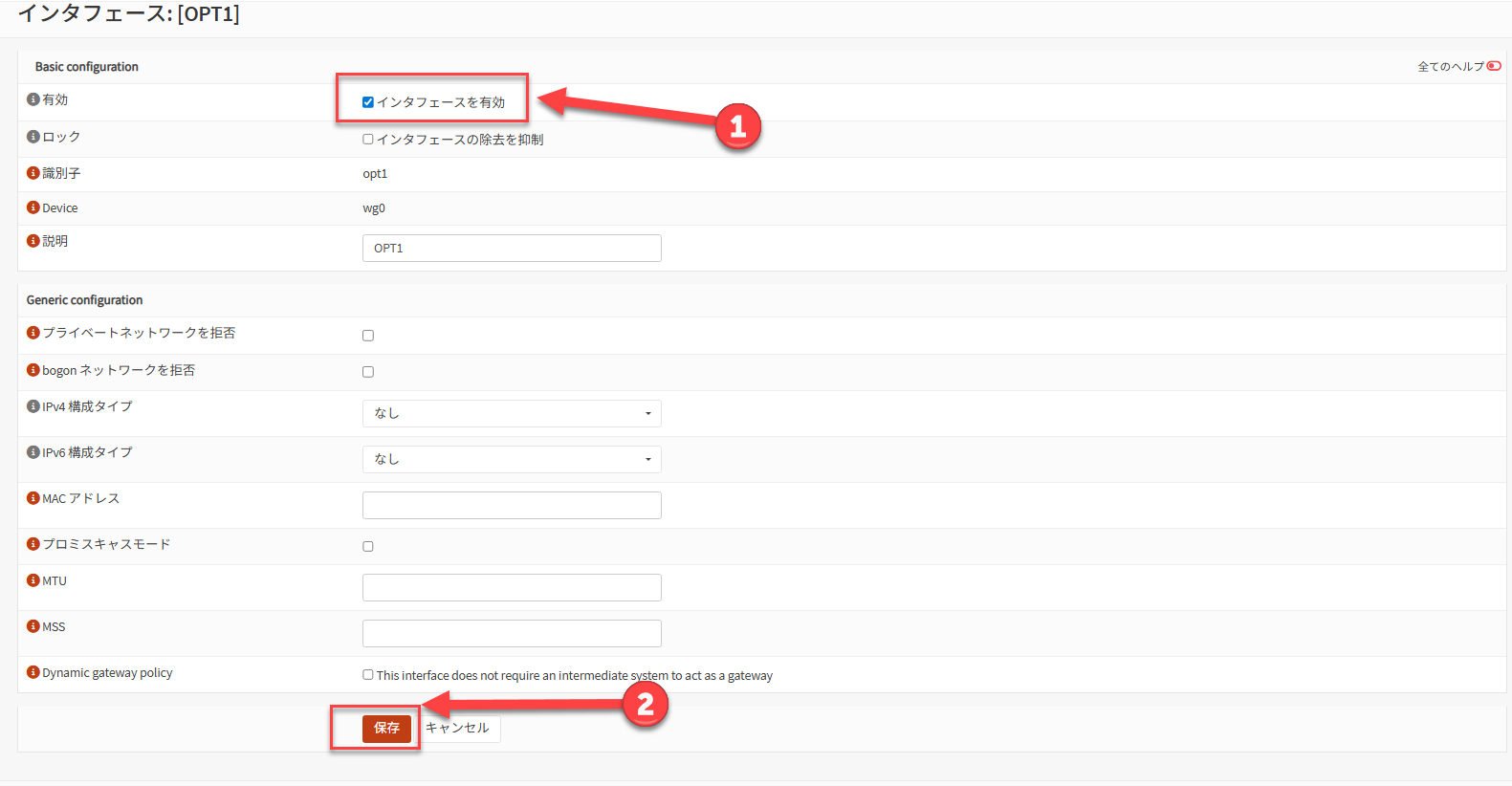
Enable the interface #
At Interfaces > OPTX, check “Enable Interface”, save, and click “Apply Changes”
| Item | Setting example | Notes |
|---|---|---|
| Enable | Checked | Enable the interface |
| Description | HomeWireGuard | Makes it easier to distinguish when creating rules |
| IPv4 Configuration Type | None | Do not manually set IP |
| IPv6 Configuration Type | None | Configure only if needed |
OPNsense official guidance indicates that you do not need to set an IP directly on the assigned interface; the tunnel address entered in the Instance is automatically reflected after a WireGuard restart.[1]
Step 4
Create firewall rules #
The official procedure uses a two-tier approach: allow UDP on the WAN side for tunnel establishment, then allow approved destinations on the WireGuard interface side.[1][2]
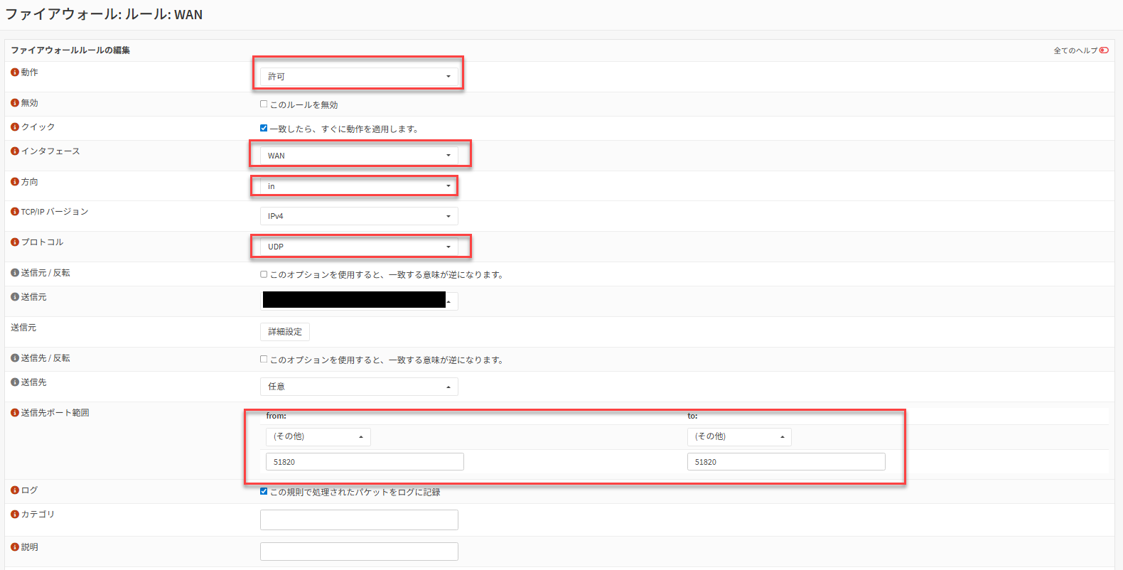
WAN side rule #
| Item | Setting example | Notes |
|---|---|---|
| Action | Pass | Allow receipt |
| Interface | WAN | WAN receive side |
| Protocol | UDP | WireGuard uses UDP |
| Destination | WAN address | Own WAN |
| Destination Port | 51820 | Must match Instance Listen Port |
| Description | Allow WireGuard | Optional |
WireGuard interface side rule #
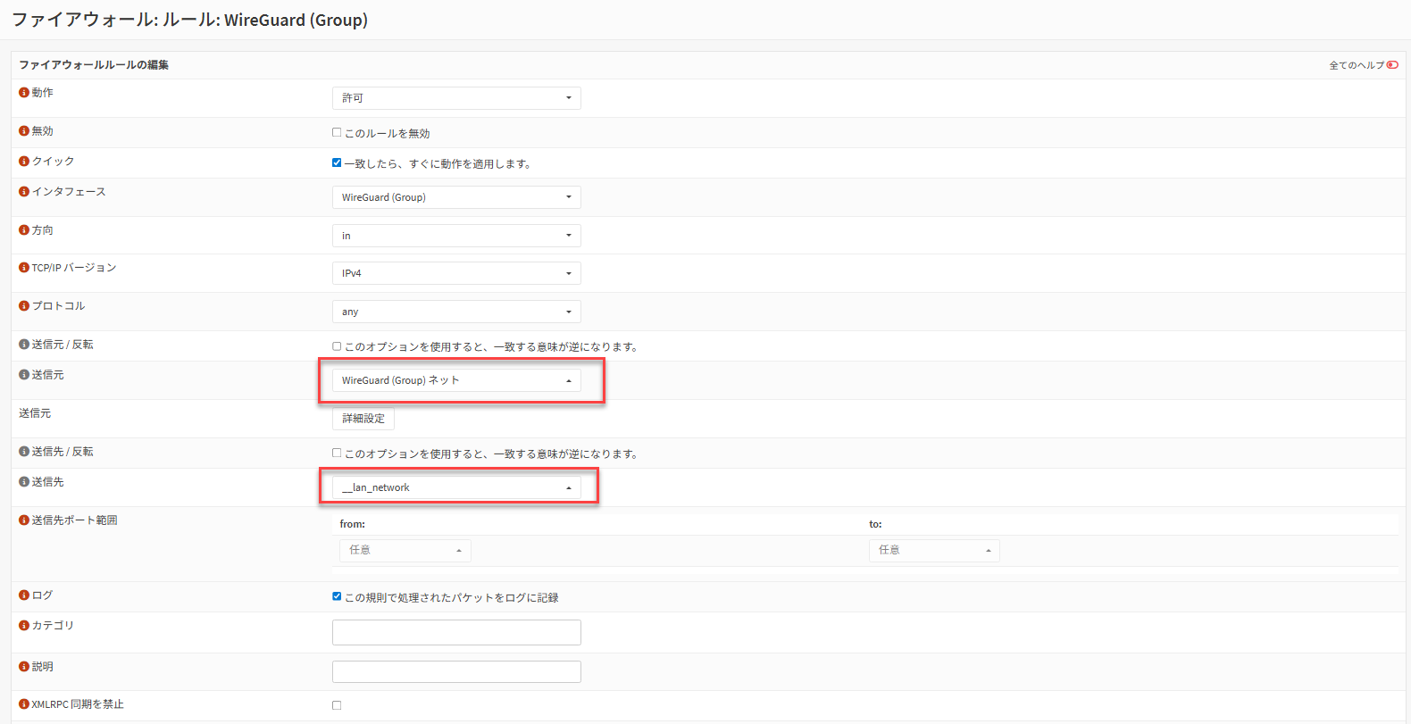
| Item | Setting example | Notes |
|---|---|---|
| Action | Pass | Allow tunnel traffic |
| Interface | HomeWireGuard | Assigned WireGuard interface |
| Protocol | any | Initially acceptable for connectivity testing |
| Source | HomeWireGuard net | Tunnel network |
| Destination | 192.168.10.0/24 | Start by permitting only LAN |
OPNsense official guidance permits setting the WireGuard rule destination to any, but in operational practice, restricting to necessary subnets and servers only is recommended.[1]
MTU / MSS adjustment for PPPoE environments or some TCP communication issues
Official guidance includes an example of lowering Instance MTU to 1412 in PPPoE environments, and further guidance on adding MSS clamping via Firewall > Settings > Normalization as needed. This is effective when symptoms such as TCP-only instability or web-only failure occur.[1]
| Item | Setting example |
|---|---|
| Interface | WireGuard (Group) |
| Description | WireGuard MSS Clamping IPv4 |
| Max MSS | 1380 (for PPPoE: 1372) |
Step 5
Deploy configuration to the Windows client #
On the Windows side, using the official WireGuard for Windows is the simplest approach. The installer is available from the WireGuard official website.[4]
- Install WireGuard for Windows.
- Prepare the
client-windows.confsaved from OPNsense Peer generator. For manual creation, use the template provided earlier. - Import the configuration file into WireGuard for Windows.
- Enable the target tunnel and begin the connection.
client-windows.conf
By including LAN segments like 192.168.10.0/24 in AllowedIPs, only that destination is sent through the tunnel. If you want to route all client traffic through the VPN, use 0.0.0.0/0 or ::/0 per official guidance, but additional NAT / routing design on the OPNsense side is also required.[1]
Step 6
Connection verification #
- Enable the tunnel on the Windows client
- Test connectivity to
10.10.10.1(OPNsense tunnel IP) - Try
ping, RDP, SSH, and other connections to a representative LAN host (example:192.168.10.10) - Test name resolution as needed and verify that DNS works
- Check handshake and send/receive statistics at
VPN > WireGuard > Status[2]
Operations
Hardening to implement before going public #
Assign /32 per Peer #
Assigning a unique /32 to each client makes it easier to track rules and logs on a per-device basis.[1]
Allow only necessary destinations #
It is safer to restrict the WireGuard interface rule destination to the LAN or specific server groups rather than leaving it as any.
Source restriction for fixed locations #
If the WAN rule source can be restricted to a fixed IP, you further limit reachable parties.
Add PSK if needed #
OPNsense Peers can have a pre-shared key added, which official guidance also recommends as an additional security measure.[2]
Troubleshooting
Checklist when connection fails #
No handshake appearing
First check WAN-side UDP 51820 allowance, upstream router port forwarding, client-side Endpoint FQDN/port, and any significant client time drift.
Handshake appears but LAN unreachable
Review Peer Allowed IPs, client-side AllowedIPs, and WireGuard interface rule destination. OPNsense official documentation also notes that incorrect Allowed IPs causes packets to drop silently.[2]
ICMP works but some web or TCP traffic is unstable
Suspect MTU / MSS impact. For PPPoE, try Instance MTU 1412 and Normalization MSS clamping.[1]
DNS fails only
Verify that the DNS destination specified on the client is included in AllowedIPs. If running Unbound DNS with all-interface registration, a Unbound reload is required after adding a new WireGuard interface.[1]
WireGuard menu not found / screen looks different
Check version differences. The Peer generator area underwent incremental improvements in the 24.1 series, and UI appearance and item arrangement vary by version.[3]
Sources
Reference Information #
- OPNsense Documentation, WireGuard Road Warrior Setup
https://docs.opnsense.org/manual/how-tos/wireguard-client.html - OPNsense Documentation, Virtual Private Networking > WireGuard
https://docs.opnsense.org/manual/vpnet.html - OPNsense Documentation, 24.1 “Savvy Shark” Series (includes Peer generator updates)
https://docs.opnsense.org/releases/CE_24.1.html - WireGuard Official, Installation
https://www.wireguard.com/install/